
How are the anchor forces in rigid base plates determined?
Load distribution for rigid base plates under bending
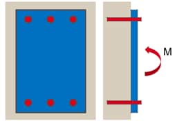
When designing anchors, loads and moments typically act on a base plate and should be transferred to the concrete via tension on the anchors and compressions in the concrete itself.
In order to design the anchorage in this situation, the forces acting on the individual anchors need to be determined. The distribution of forces and moments acting on the plate to the individual anchors can be traditionally calculated according to a rigid base plate assumption. More information about load distribution can be found in ETAG 001 – Annex C (section 4.2) and EN1992-4 (section 6).
In PROFIS Engineering, when calculating the load distribution to the anchors (while considering a rigid base plate lying on concrete), the following assumptions are taken:
• The anchor plate does not deform under design actions. Therefore, the anchor plate needs to be sufficiently stiff (a rigid base plate).
• Anchors do not take compression loads and the anchor stiffness corresponds to the modulus of elasticity of the steel (Figure 1).
• Concrete does not take tension loads. The concrete stiffness corresponds to the modulus of elasticity of the concrete (Figure 2).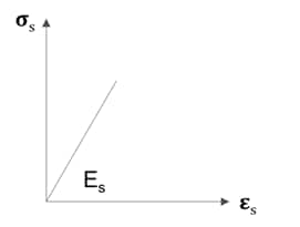
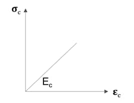
Figure 1: Linear behavior of steel (tension only) Figure 2: Linear behavior of concrete (compression only)
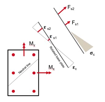
Assuming the rigid base plate, the equilibrium of forces can be understood as follows:
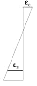
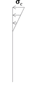
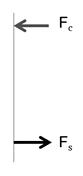
Strains Stresses Forces
Figure 3: Equilibrium of forces, assuming rigid base plate
Note that, for reinforced concrete design, the approach taken for rigid base plates corresponds to Bernoulli’s hypothesis that plane cross sections are assumed to remain plane under bending.
In practice, the following steps are taken to determine the anchor forces:
1.Determine the strain in the concrete and in the anchors.
2.Determine the stresses introduced into the concrete and the anchors.
3.Determine the forces in the concrete and the anchors.
Before the stresses can be evaluated, the neutral line must be calculated. For simple geometries and uniaxial bending, it can be quite simple to determine the load distribution by hand calculation.
For more complex geometry, the process requires a calculation of several iterations, until a solution can be found.
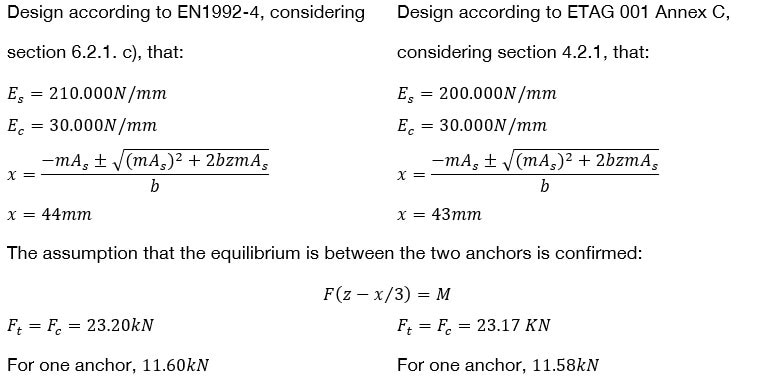
Simple example of calculating anchor forces under uniaxial bending:
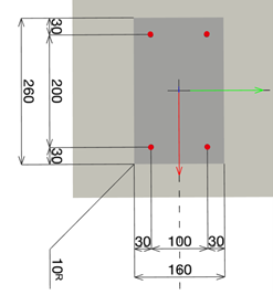
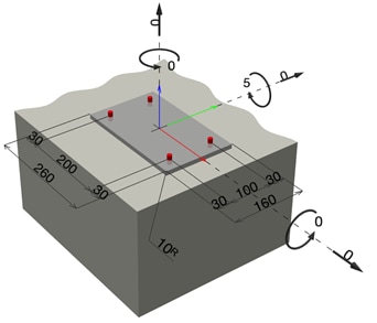
Figure 4: Uniaxial bending example
Base plate geometry Equilibrium, assuming that the neutral line is between the two anchors
b = 160 mm
l = 260 mm
s1 = 100 mm
s2 = 200 mm
z = 230 mm
Anchor HDA, M10
d = 10 mm
As = 58mm, for 2 anchors As =116mm2
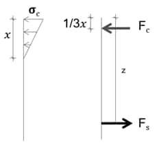
This assumption should be confirmed, once the position of the neutral line is known.
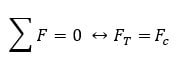
Where:
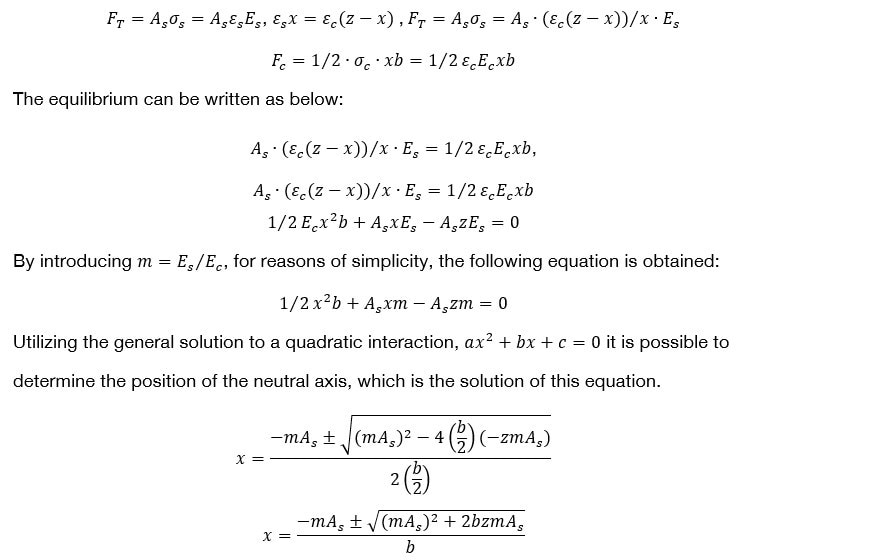
Bi-axial bending
More complex examples, such as biaxial bending, always follow the same equilibrium and compatibility conditions. However, it is typically less easy to solve these equations by hand calculation as it will take quite a number of iterations until the final solution is determined.